5.5.1 Single/single Sprayed Seal
A general schematic of the process for determination of binder and aggregate application rates for single/single seals is shown in Figure 5.2.
Figure 5.2: Flow chart for design of a single/single seal
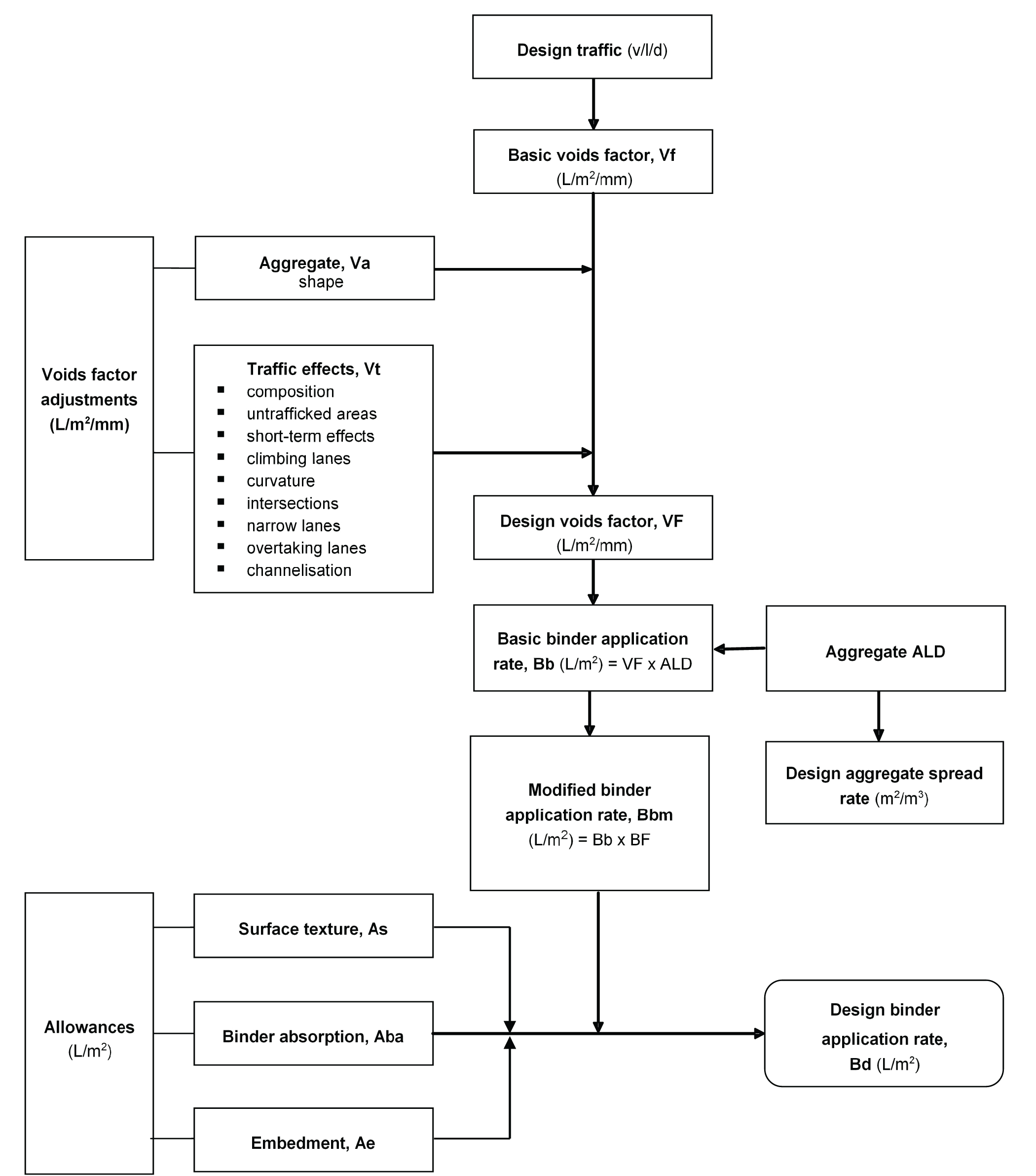
The design procedure is as follows:
- Determine design traffic (Section 5.2).
- Determine basic voids factor, Vf (Figure 6.1 or Figure 6.2).
- Apply voids factor adjustments (Section 6.1.2)
- Aggregate, Va
- Traffic effects, Vt.
- Calculate design voids factor, VF (Section 6.1.3).
- Determine basic binder application rate, Bb (Section 6.2.1).
- Determine modified binder application rate, Bbm (Section 6.3.1).
- Apply allowances
- Calculate design binder application rate, Bd (Section 6.4).
- Determine design aggregate spread rate (Section 6.7.3).